|
RICHARD T RITTER
|
ULF CAMERA SPECIFICATIONS 11 x 14
|
|
|
|
|
SPECIFICATIONS 11 x 14 |
Front shift 6.5 (165mm) total movement
Standard bellows 34 inches
Custom options available:
DVD User Manual Ordering information
|
Rear swing 25 degrees
Standard lens board
Current Cost $4785
|
|
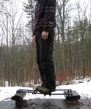
Testing for rail strength |
The Rail System The underlying strength of a camera comes from the platform
on which the working components are placed, the lens, and the sheet of film. The
modern-day field camera design has not changed much in the last 125 years --
wood sliding in wooden groves, with gear racks set into the rail to be driven by
gears on a shaft. This same shaft is also used to prevent the rail from sliding
in and out when locked. This system works well on small cameras, 4x5 thru 8x10.
The rails are short, and the up-and-down play from the necessary
clearance is not noticeable. This
changes as the cameras get bigger. The play that is inherent in bigger cameras has been a problem for a very long time. To address the problems I and others were having in dealing with this inherent play, I realized I had to think outside the box. I knew two things would not change. They were the front frame that held the lens and the rear ground glass frame and back that held the film holder. I started with a simple look at all the different traditional materials and composites available, along with looking for the best weight-to-strength ratio I could find. The starting point was the weight to strength ratio number I got from figuring out the strength of the average wooden rail on ULF cameras. I started with round aluminum tubes; they worked and they didn�t. After some use and a lot of abuse, the aluminum�s sliding action started to get rough and gritty-sounding, as the rails were slid back and forth (this is an inherent problem with aluminum). After some more testing, I settled on carbon fiber tubes. See photo to the left of the rail system fully extended. The overall design of the camera was to be modular, with one rail able to handle multiple format sizes. The ULF rail will cover sizes from 7x17 to 20x24. Standard extended length is 34 inches; longer or shorter rails can be custom ordered.
|
|
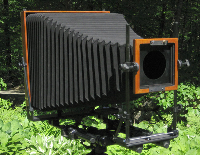
The Camera Body The body of the camera is wood. It comes with a bail back for ease of loading and unloading the film holder. The panoramic bodies can be changed from vertical to horizontal in the field, keeping the weight of the camera over the tripod. Format size can be easily changed. Release the front bellows frame from the front, undo two locking knobs, and the back with attached bellows is released from the rail system. A different size back can now be put on the rails. More information on the design.
|
|
|
|
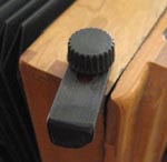
Sliding lock and lock knob
|
It has been assumed by some that the way the back rotates from horizontal to vertical on the 8 x 10, 11 x 14, 14 x 17, 16 x 20 and 20 x 24 cameras is that the back, box, bellows ect come off and rotate the same way as the panorama camera. This is wrong. After years of working with and on cameras with different ways of holding the back on I settled with a design that was first used on a camera in 1870. See photo. It is a combination of sliding lock and lock knob. I found this to be the best. Why? Pins: As used on Deardorf, Wisner, D2. ect. Pins have to be drilled to the camera back and hardware of each camera, are hard to interchange backs with other cameras. The area where the pins are located sometimes breaks away. The closing hardware wears out and breaks. Pins fall out. The back rattles around due to sloppy holes. I have also had backs fall off the camera from the hardware getting caught on a branch and releasing the back from the body of the camera or the pins just did not catch right and the back just pops off when you turn your back to the camera. Sliding lock: Wisner, Zone VI. The locking hardware when transporting the camera over the shoulder on a tripod sometimes catches on a branch and pulls the sliding lock open allowing the back to drop off. Sliding lock with lock knob (see photo). Positive locking system of the back to the body of the camera, nothing for branches to get caught on and release the back from the camera. System works by loosing the lock knob a half turn and sliding the bracket out of the way. Turn back and reverse the steps. No worry of the back falling off the camera when transporting the camera on a tripod through brush and branches.
|
|
|
|
|
|
|
|
For more info contact
Click here
Richard T Ritter
(802)-365-7807
©2023 RTRitter